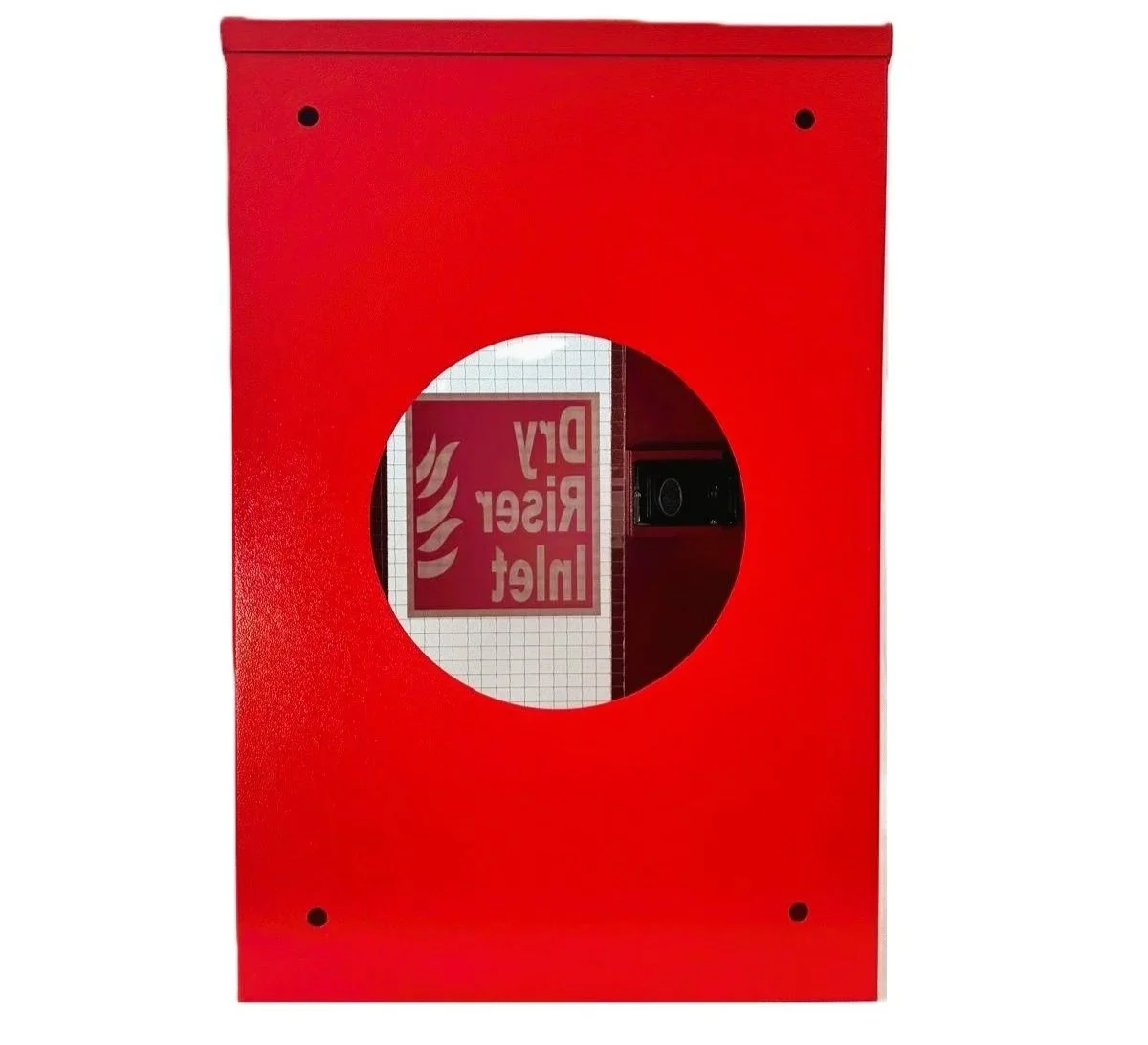
Installing a dry riser inlet cabinet is not always as straightforward as forming an opening in an external wall. On refurbishment projects, existing buildings and some new developments, structural restrictions can make installing a traditional recessed inlet cabinet difficult or impractical. A surface-mounted dry riser inlet cabinet provides an alternative installation method, allowing the 2-way breeching inlet to be housed externally without creating a large rectangular recess in the building façade.
In this guide, Dry Riser One Ltd explains how surface-mounted dry riser inlet cabinets are installed, how they are secured to external walls, how the connecting pipework can be arranged and what to consider when structural engineers restrict the size of wall penetrations.
Planning a Surface-Mounted Dry Riser Inlet Installation
Before installing a surface-mounted cabinet, the proposed location and pipework arrangement must be carefully assessed. The client should design↗︎ and establish the position of the dry riser inlet, the construction of the external wall, the route of the connecting pipework and whether any structural openings are permitted.
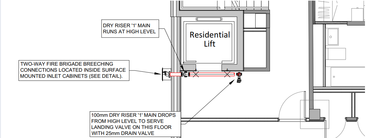
The inlet must be positioned where firefighters can safely and conveniently access the breeching inlet during a fire emergency. Consideration should be given to finished floor level, door-opening clearance, nearby building services, pedestrian routes and the location of the dry riser system. Early coordination is especially important where the building has already been constructed or where façade works are approaching completion.
Installing a Cabinet Where Large Structural Openings Are Not Permitted
One of the main practical advantages of a surface-mounted dry riser inlet cabinet is that it can avoid the need to form a large rectangular wall recess. For example, a structural engineer may reject a proposed wall opening measuring approximately 595 mm × 395 mm due to concerns about the existing construction. Such restrictions can arise where the wall is load-bearing, contains reinforcement, or is positioned close to other structural openings.
In some cases, the engineer may permit a smaller circular core hole, such as 150 mm in diameter, subject to its location and the proposed installation detail. Rather than cutting a large opening to accommodate the cabinet, the surface-mounted inlet cabinet can be fixed directly to the outside face of the wall.
The connecting pipework may then pass through an appropriately designed penetration (usually 150mm in diameter) into the building, where it connects with the internal dry riser system.
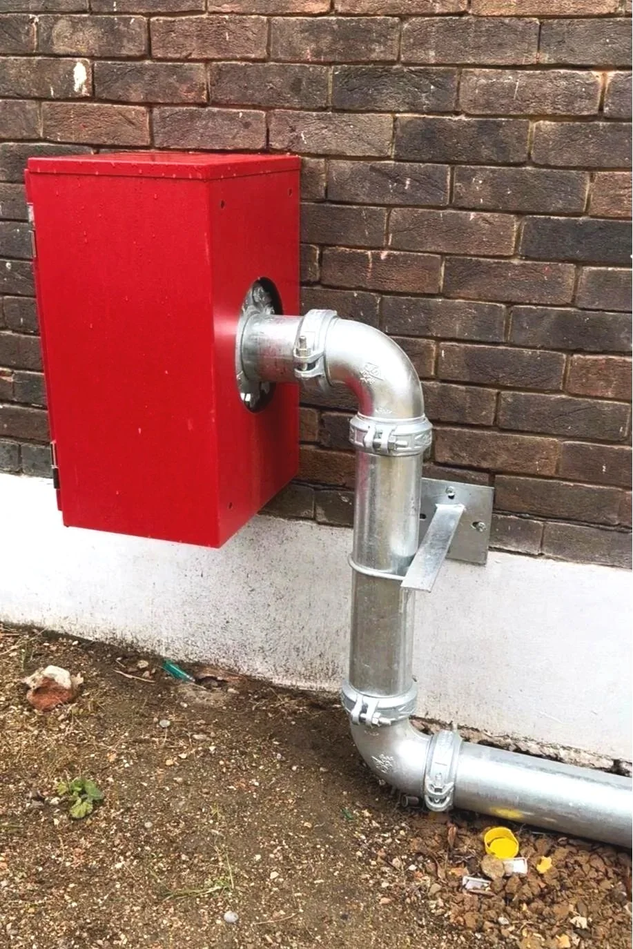
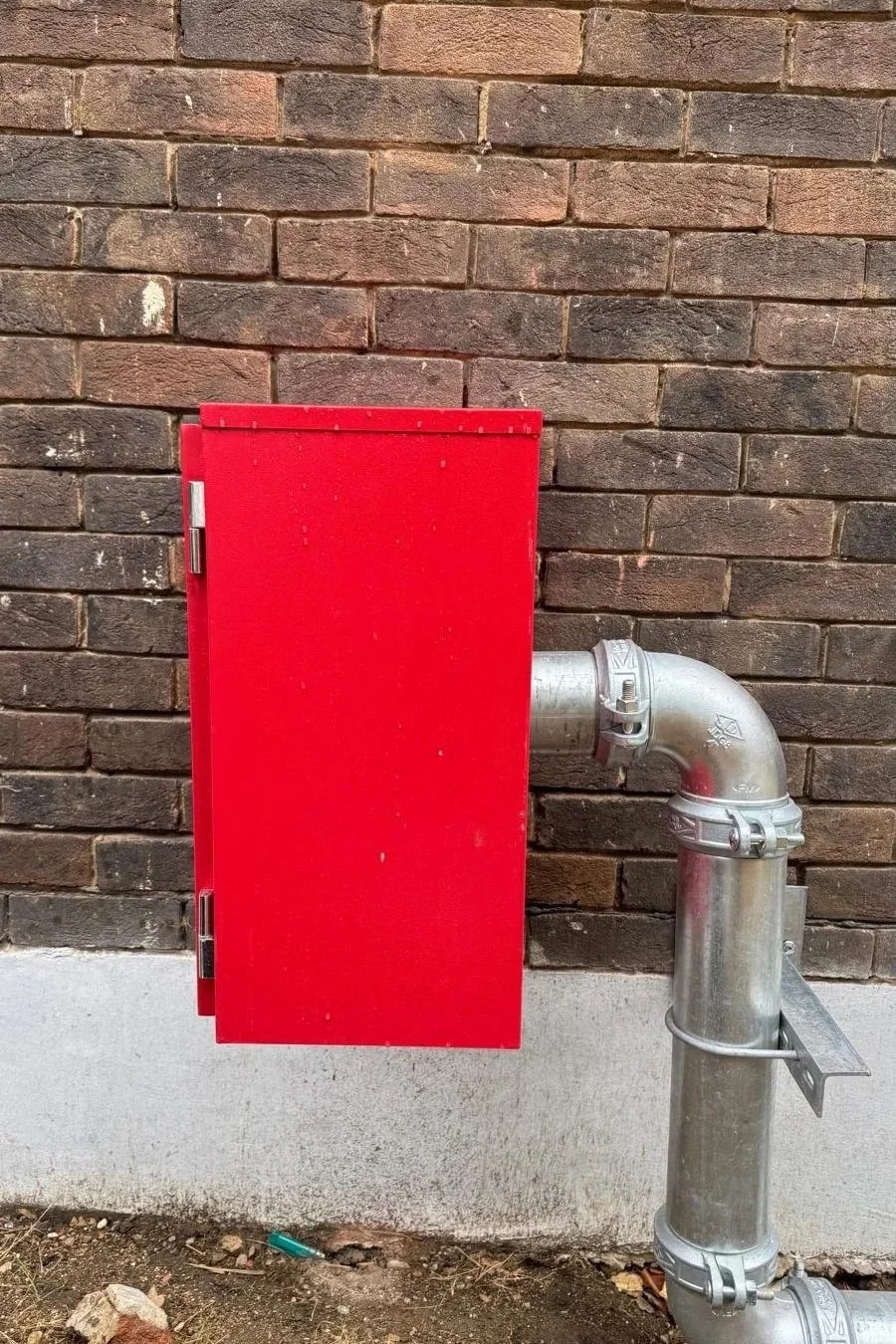
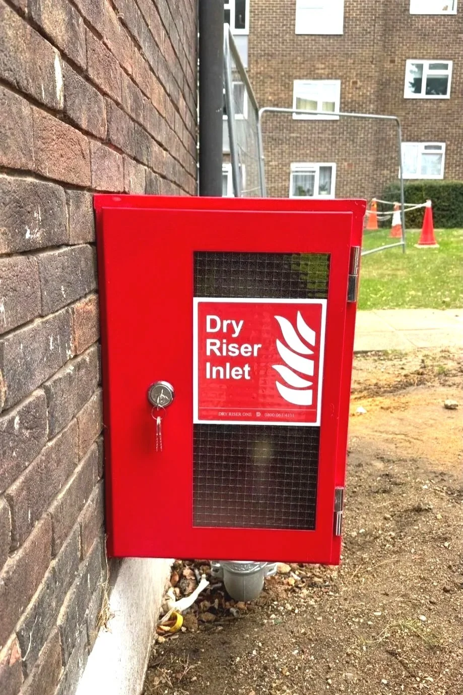
How to Fix a Surface-Mounted Dry Riser Inlet Cabinet to an External Wall
Surface-mounted cabinets are generally designed with rear fixing provisions, enabling the cabinet to be secured to a suitable wall or supporting structure. For example, the surface-mounted inlet cabinet has four 12 mm diameter fixing holes in the rear panel. The installation process typically involves the following stages.
Step 1: Inspect the wall construction
The installer should confirm whether the wall consists of solid brickwork, concrete, blockwork, cavity construction or another façade system. The condition and load-bearing capability of the proposed fixing points must be assessed before drilling (*). For cavity walls or non-structural facing materials, a designed fixing arrangement may be required to transfer loads to the supporting structure.
Step 2: Set out the cabinet position
The cabinet location is marked against the approved installation drawings (*). The installer checks that the cabinet is correctly aligned with the breeching inlet and any connecting pipework. There must be sufficient room for the door to open fully and for firefighters to connect their hoses.
Step 3: Drill and prepare the fixing points
Once the approved fixing locations have been established, the wall is drilled to suit the specified fixing system. Suitable fixings may include anchors or an appropriately specified resin-anchor system, depending on the supporting material and project requirements. (*)
Step 4: Secure the cabinet
The cabinet is positioned against the wall and secured using the approved fixings. The installer checks the alignment, stability and operation of the access door.
Step 5: Check the completed installation
The completed fixing arrangement is inspected to ensure the cabinet is secure, correctly positioned and free from distortion. The door, hinges, lock and inlet identification must remain fully functional. Importantly, the cabinet should not be used to support the weight or operating loads of the associated dry riser pipework unless that arrangement has been specifically engineered.
* Important: Before commencing any of the works described above, you must consult a suitably qualified structural engineer and your local Building Control authority to confirm that the proposed works are structurally safe, comply with applicable Building Regulations, and have received any necessary approvals. Do not proceed until all relevant assessments, permissions and approvals have been obtained.
Cabinet Positioning and Fire Service Access
A properly installed inlet cabinet must remain accessible to the fire and rescue service. The cabinet should be clearly identified with DRY RISER INLET signage and positioned in accordance with the approved fire strategy and BS 9990 guidance↗︎.
Its position should be coordinated with the building entrance, fire appliance access arrangements and the route of the dry riser. The installation should also account for permanent and temporary obstructions. Landscaping, parked vehicles, fencing, bin stores, scaffolding and external building services can all affect the practical accessibility of an inlet.
Where the surface-mounted cabinet projects into a pedestrian area, the risk of obstruction or impact damage should be assessed. Access must remain suitable after the completion of all external construction and landscaping works.
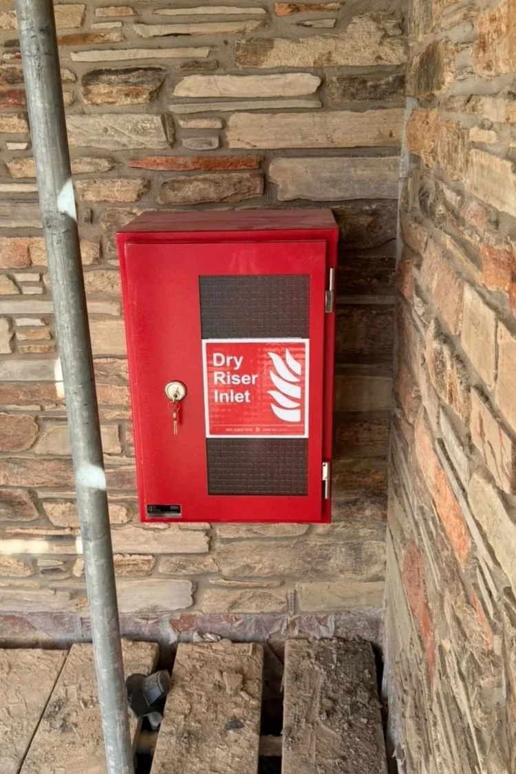
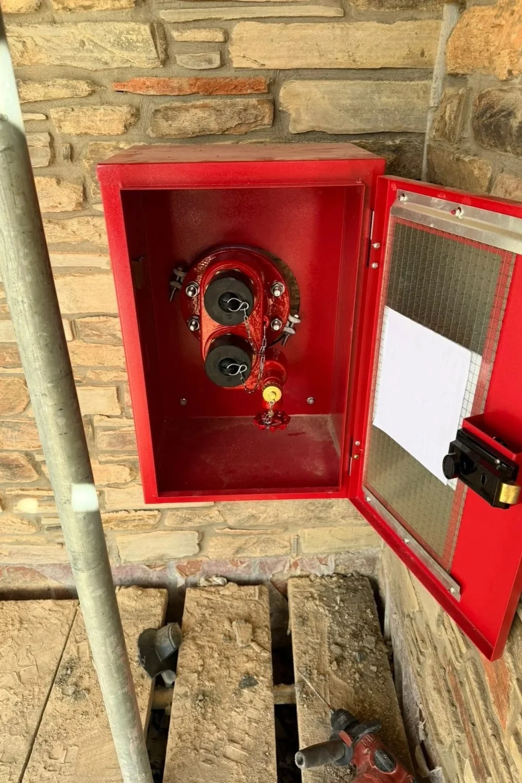
Testing and Commissioning After Installation
Following installation, the dry riser system must undergo the appropriate inspections and commissioning procedures. These include checking the breeching inlet, connecting pipework, couplings, supporting brackets, drain arrangements and as such.
The completed system must undergo the 12 Bar pressure testing in accordance with BS 9990:2015↗︎. The surface-mounted cabinet should also be inspected to verify that its fixings are secure, the door operates correctly and the inlet connections are accessible. Any defects identified during commissioning must be resolved before the system is handed over.
Professional Surface-Mounted Dry Riser Inlet Installation
At Dry Riser One Ltd, we understand the challenges associated with installing dry riser systems in existing buildings, refurbishment projects and developments with structural restrictions. Surface-mounted dry riser inlet cabinets can provide installation flexibility where recessed arrangements are not practical. Whether the project involves a restricted structural opening, a rear-entry connection or externally routed galvanised pipework, careful design coordination is essential to achieve a reliable and maintainable system.
Planning a dry riser installation with restricted wall openings?
Contact Dry Riser One Ltd to discuss your project requirements and suitable installation arrangements.
For cabinet dimensions, materials and purchasing information, visit our Dry Riser Surface-Mounted Inlet Cabinet product page.
Technical note: This guide describes general installation principles. Structural penetrations, anchor selection, pipework supports and fire-stopping must be designed and approved for the particular building. The installation must follow the relevant project fire strategy, applicable standards and manufacturer instructions.
Sources: