Dry Riser Design
Introduction to Dry Riser Design
A Dry Riser Design is a critical aspect of fire safety in multi-storey buildings.
A properly designed dry riser system allows firefighters to quickly deliver water throughout the building during an emergency, significantly improving response time and reducing the spread of fire. In tall buildings, using fire hoses at ground level can be difficult and unsafe. Dry Risers help solve this problem. They are permanent vertical pipes inside the building that firefighters can connect their hoses to. This lets them send water to different floors quickly and safely.
This guide provides an overview of dry riser design, including layout details, pipe sizing, landing valve spacing and installation and testing procedures.
Dry risers must be designed and installed to British Standards. The two important standards are BS9990 for non-automatic fire fighting systems and BS9999, which provides guidance on fire safety in building design.
What is a Dry Riser System?
A dry riser is normally empty steel pipe installed inside a building that allows firefighters to pump water from the ground level to upper floors. Besides annual testing, a dry riser is only filled with water when the fire and rescue service connect their pump appliance to the inlet valve.
A typical dry riser system includes the following:
External breeching inlet
Horizontal and rising steel pipework
Landing valves at each floor
Drain valves
Air release valves
Inlet and Outlet Cabinets and signage
During a fire emergency, firefighters connect hoses from a pump appliance to the breeching inlet, forcing water through the pipework to the landing valves on the upper floors. This allows firefighters to access water close to the location of the fire.
Key points when designing dry risers
Accessibility: Breeching inlets and landing valves must be positioned so firefighters and easily connect hoses while remaining protected from the fire and smoke.
System Coverage: The dry riser landing valves must allow firefighters to reach every part of each floor using standard hose lengths (45-metres).
Hydraulic calculations: Pipe sizes, lengths and system heights must allow adequate water and pressure flow.
Fixings: Horizontal and vertical pipes must be securely fixed to the building structure using industry approved brackets.
The following section explains the dry riser design process and how these systems are developed in practice.
Main components of a Dry Riser System
Knowing the components of a dry riser is key when designing the system.
Breeching inlet: This is the main connection point used by firefighters to pump water into the system. The breeching inlet should be within 18 metres of the fire appliance with clear signage and protected within a glass fronted cabinet.
Galvanised steel pipework: This is the horizontal and vertical pipe that carries water from the breeching inlet to the upper floors. The pipe diameter is typically 100mm, however larger developments may require 150mm. Pipework must be fixed at regular intervals to prevent movement when the system is on test.
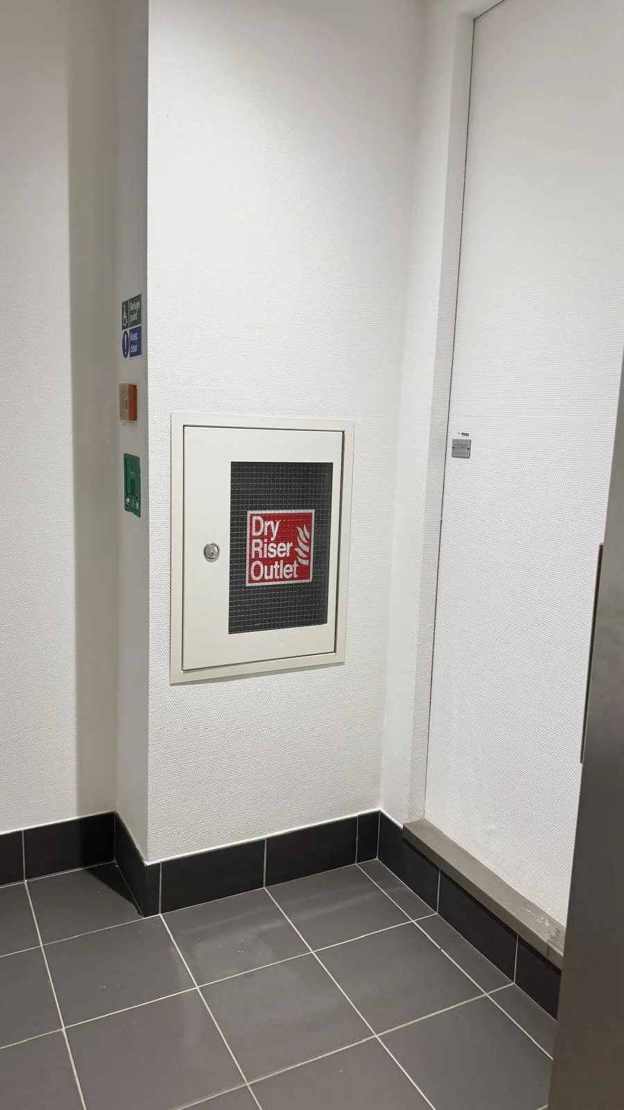
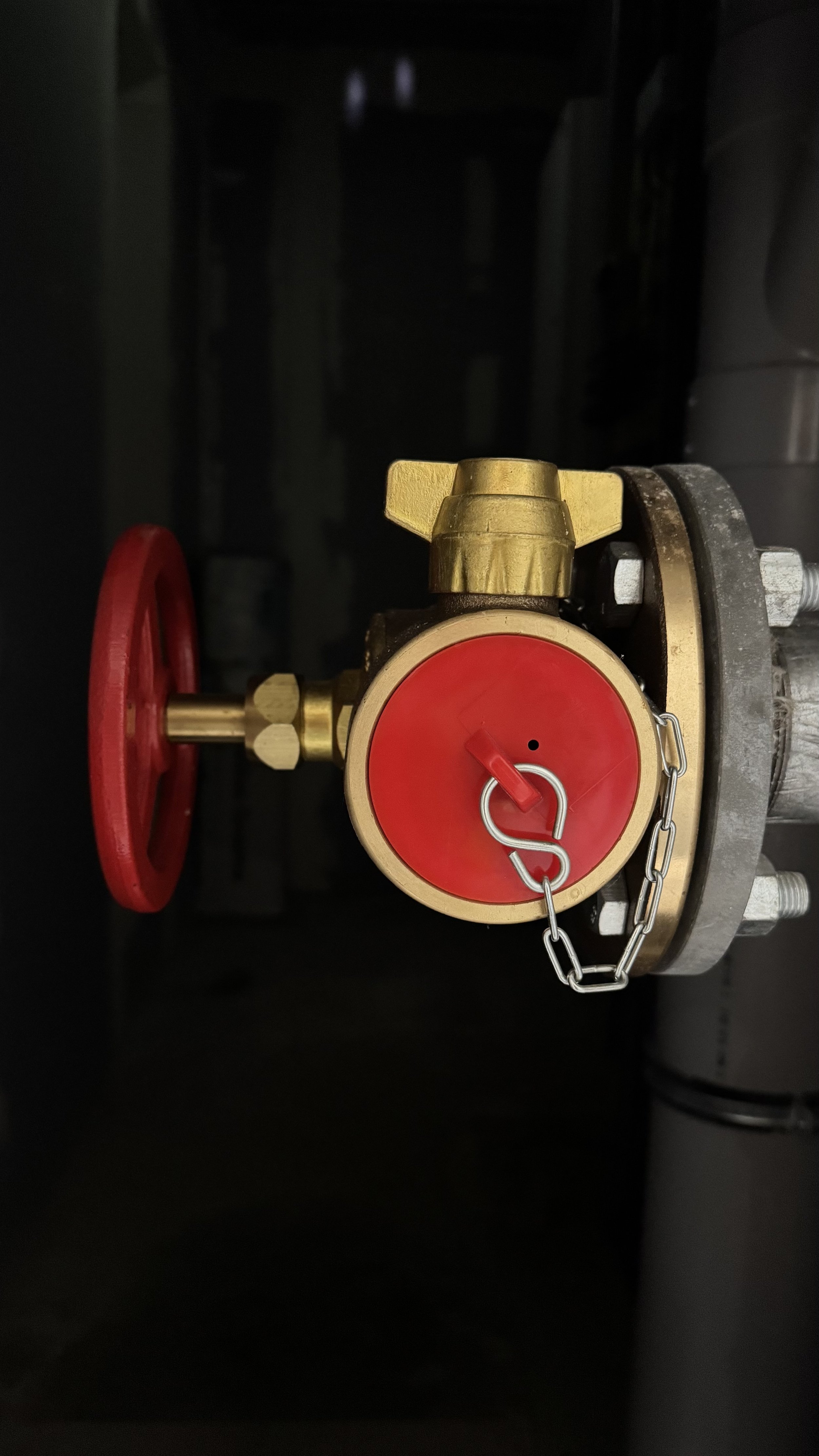
Landing valves: Also known as outlets, landing valves should be installed on every floor to allow firefighters to connect hoses. They should be designed into protected stairwells and easily visible for firefighters. Landing valves are normally housed in glass fronted enclosures to ensure easy identification and lower the risk of theft.
Drain valves: Drain valves allow water remaining in the pipe after testing or firefighting to be discharged. This prevents the pipe from corroding inside and freezing.
Air release valve: Air release valves allow trapped air to escape when the system is filled with water during testing or firefighting.

The Evolution of Dry Riser System Design
The design of dry riser systems has undergone significant evolution in response to the rapid development of high-rise buildings, particularly in the 20th century. As urbanisation increased and skyscrapers became more common, the need for more efficient and effective fire safety systems grew. Dry riser systems were developed and refined to meet the challenges posed by tall structures, offering a streamlined method for firefighters to access water quickly and efficiently during emergencies.
Dry Riser Systems began to appear in the 1950s, providing a permanent vertical pipe system inside buildings. These early systems allowed firefighters to pump water from a fire appliance at ground level directly to landing valves on upper floors, significantly improving response times during emergencies.
Early dry riser designs were relatively simple, typically consisting of basic steel pipework with landing valves installed at each floor level. While functional, these systems lacked many of the design refinements and safety considerations used in modern installations.
Over time, the design of dry riser systems has evolved alongside improvements in building regulations and fire engineering. Modern dry riser systems must comply with British Standards such as BS 9990 and BS 9999, which provide detailed guidance on system layout, pipe sizing, valve positioning, accessibility, and maintenance requirements.
Today, dry riser design forms an essential part of a building’s overall fire strategy, ensuring firefighters can access water quickly and safely throughout the structure during an emergency.
The following section explores modern dry riser design techniques and how engineers use AutoCAD to develop detailed system layouts.
Designing Dry Riser Systems Using AutoCAD
With the development of modern design software such as AutoCAD, dry riser systems can now be planned with far greater precision. Engineers are able to model pipe routes, landing valve positions, and system layouts in detail, ensuring that installations comply with current regulations while integrating efficiently with the building’s structure and other services.
Dry Riser Design Process
The dry riser design process typically begins when the designer receives the floor plans and building sections from the main contractor or project team, along with the fire strategy drawings for the development.
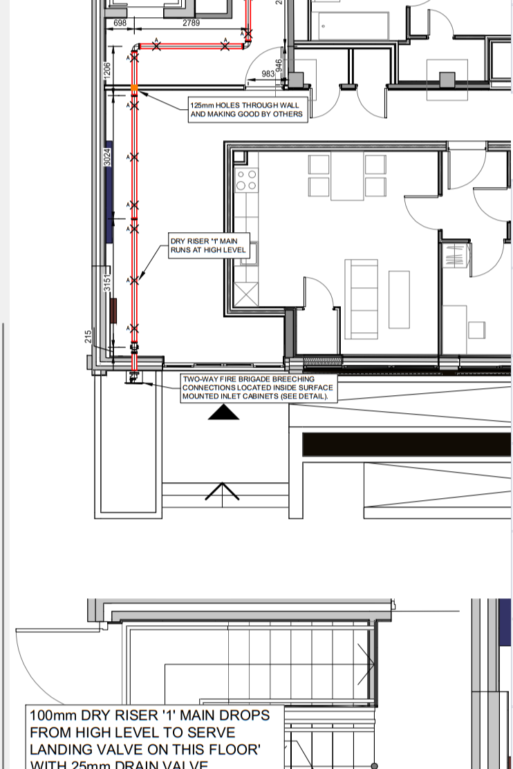
These drawings normally indicate the required locations of the dry riser outlets within the building. Using this information, the designer produces the dry riser layout, showing the position of pipework, landing valves, inlet boxes, and associated components.
Design Approval Stages
Dry riser design drawings usually go through several stages before installation begins.
Design for Approval: The initial design drawings are produced and issued for review by the project team, fire consultant, and building control.
Approved Design: Once the drawings have been reviewed and accepted by the relevant parties, including Building Control, the design is formally approved.
Once design is approved you are ready to go and can start the dry riser installation process.
This structured design and approval process ensures that the dry riser system is fully compliant with fire safety regulations and suitable for the building’s layout before installation begins.
News & Articles