
Dry Riser Installation in Hertfordshire with an Underground Section
Dry Riser One Ltd provided the underground installation (Phase 1) for a residential dry riser project in Hertfordshire. The scheme combines a below ground connection from the fire breeching inlet with a planned vertical riser serving the building’s ground, first, second and third floors.
Our involvement included preparation of the dry riser design drawings and installation of the underground section, with pressure test photographs recorded on 29 September 2026. Between the breeching inlet and the internal riser needs attention early in the construction programme.
Designing the dry riser system for the residential development
The design package covered the ground floor, three upper floors and a building section. Together, these drawings set out how the inlet, underground main, vertical pipework and landing valves would connect across the development.
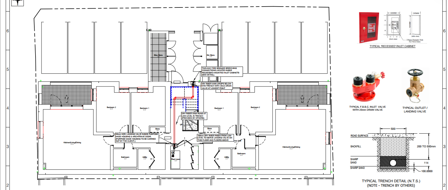
The proposed arrangement uses a 100 mm dry riser main and 65 mm horizontal landing valves. The section drawing shows four outlet positions, one at each level from ground to third floor, with an air release valve at the uppermost outlet arrangement. The external connection is shown as a two way fire brigade breeching inlet in a recessed cabinet.
Preparing both floor plans and a section helped explain the route in three dimensions. The ground floor plan shows the horizontal connection from the inlet towards the internal riser, while the section shows the drop below ground and the rise through the building. This makes the relationship between the external works, entrance lobby and upper floor outlets easier for the project team to review. The drawings were issued as design intent, with Revision B dated 26 September 2026. This provided a coordinated layout for review, while recognising that final pipework and equipment locations could change on site.
Our dry riser design service supports this planning stage by setting out pipe routes, inlet locations, outlet arrangements and other installation details.
Planning the underground dry riser connection
The underground section links the external inlet position to the point where the dry riser system rises inside the building. On this project, the proposed route drops below ground near the inlet and travels through a trench before connecting to the internal vertical pipework.
That connection needs to be considered alongside the surrounding construction. The pipe route, changes in direction, entry into the building and access to drainage components all affect how the installation fits into the development. The design drawings included a typical trench detail and a proposed underground drainage arrangement. They also identified trenching, backfilling, chamber construction and associated builders’ work as responsibilities of others. Recording these interfaces gives the project team a clearer basis for planning the sequence of works.
Installing the underground section in Hertfordshire
The design specifies galvanised steel pipework with grooved fittings and couplings. These details establish the intended pipework arrangement, while the site photographs record the stage of construction at the time of the underground works.
The underground connection is an important part of the overall dry riser route. Once surrounding construction and backfilling are complete, access to buried components becomes more difficult. Recording the works while the area remains accessible therefore provides useful information for the project record and later coordination.
This Rickmansworth project follows other below groundwork undertaken by our team, including our underground dry riser installation in Salford.
Incorporating drainage into the proposed layout
The design package includes a drainage facility associated with the below ground pipework. The section details show a drain valve and plug within an underground chamber, together with access from ground level.
Including this arrangement in the drawings brings drainage into the design discussion before the surrounding works are finished. The project team can review the relationship between the inlet, underground main and chamber rather than treating the drainage point as a separate item to resolve later.
The drawings also identify the chamber and purpose made housings as work to be provided by others. This distinction helps define the dry riser installation scope and the supporting construction needed around it.
Pressure test evidence at the start and after 15 minutes
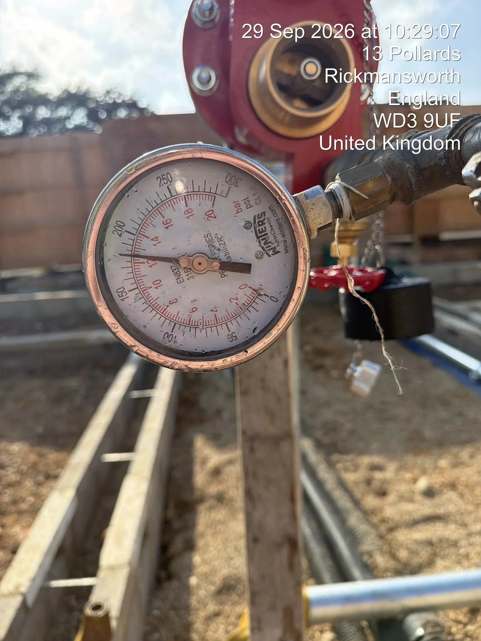
The underground works were supported by pressure test photographs taken on 29 September 2026. The first photograph is timestamped 10:12:24, and the later photograph is timestamped 10:29:07.
These records are 16 minutes and 43 seconds apart, placing the later photograph beyond the 15 minute point. Both photographs show the gauge indicating approximately 12 bar, with no obvious change visible between the two images. Showing the start and later readings together gives the project team a useful visual comparison. It records the indicated pressure at two points in time and supports the documentation of this installation stage.
The photographs relate to the underground works described here. Final commissioning and certification of the complete dry riser system are separate stages and should be documented through the relevant inspection and test records.

Dry riser design and installation in Hertfordshire
This project demonstrates our involvement in the design and underground installation stages of a residential dry riser system in Rickmansworth. The drawing package explains the intended route across four levels, while the site photographs record the underground works and pressure gauge readings taken more than 15 minutes apart.
For developers and contractors planning dry riser works in Hertfordshire, early review of the building layout and below ground connection helps establish the scope before installation begins. Floor plans, building sections and the project fire strategy provide the starting point for that discussion.
To discuss dry riser design, installation or an underground connection for your project, contact Dry Riser One Ltd on 0800 061 4111 or email enquiries@dryriserone.co.uk.
Follow us on Instagram for more site updates and examples of the dry riser projects we complete across Hertfordshire and the UK.