
Dry Riser Gate Valve Flanged
Product Specifications
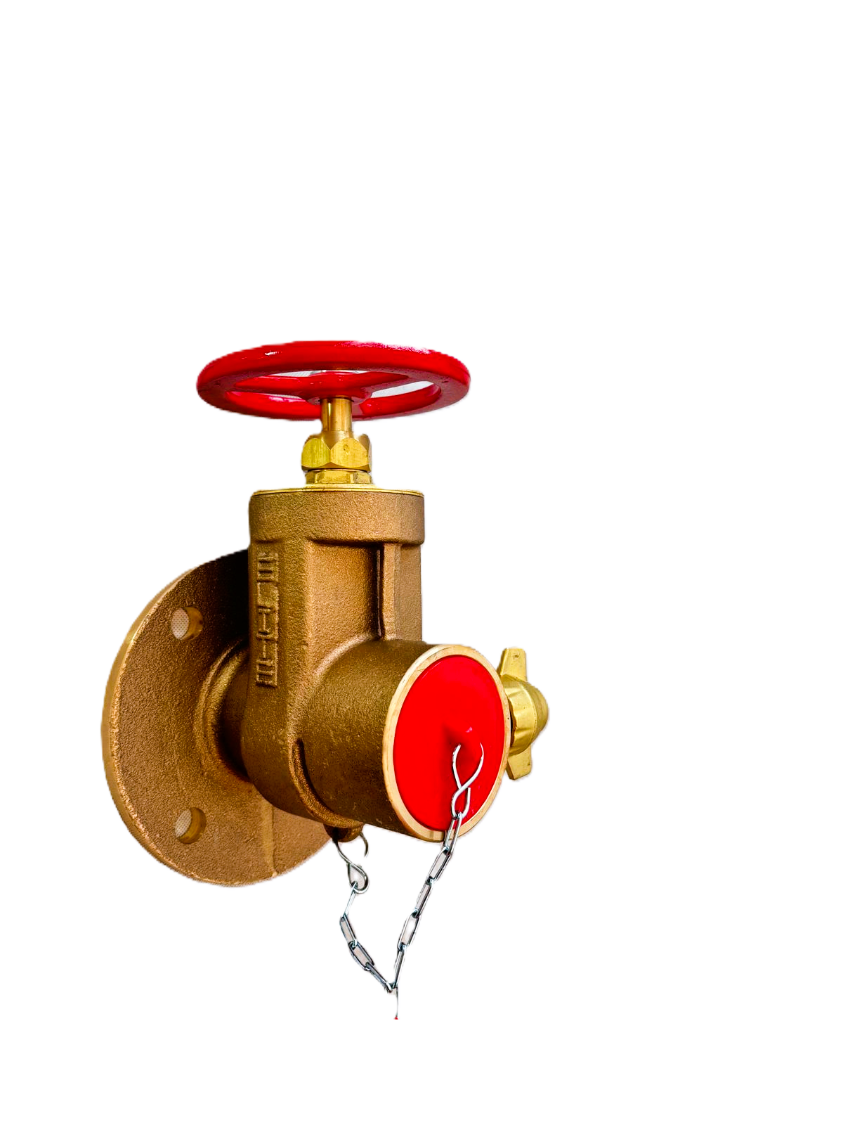
Product specification details for the Dry Riser Gate Valve – Table D include:
Product Name: Dry Riser Gate Valve – Table D/E
Inlet: Flanged Table D/E inlet
Material: Corrosion-resistant gunmetal construction
Operation: Handwheel operated gate valve
Valve Cap: Supplied with valve cap and chain
Compliance: Manufactured in accordance with BS5041 Part 2
Hydrostatic Testing: Tested to 16.5 bar and 22.5 bar
Dimensions: 160mm high x 300mm wide x 410mm deep
Weight: Approx. 7.28kg
Product Features
The Dry Riser Gate Valve – Table D/E is designed for reliable dry riser outlet use and provides a standard connection point for Fire Brigade hose attachment.
Key features include:
Corrosion-resistant gunmetal construction.
Suitable for onshore and offshore applications
Manufactured in accordance with BS5041 Part 2.
Flanged Table D/E inlet.
Hydrostatically tested to 16.5 bar and 22.5
Supplied complete with handwheel and valve cap.
The gunmetal construction provides durability and corrosion resistance, helping ensure a long usable life in demanding environments.
Product Use and Protection
The Dry Riser Gate Valve – Table D is designed for use as part of a dry riser system, allowing the Fire Brigade to quickly connect layflat hose to the system during an emergency.
The valve is suitable for use in both onshore and offshore applications and is commonly used in industrial, marine, petrochemical, oil and gas, aviation, nuclear, waste recycling, and fire and rescue service environments.
When the dry riser system is charged from the inlet at ground level, the outlet valve allows water to be controlled and discharged at the required floor or firefighting access point.
The valve cap and chain help protect the outlet connection from dust, rubbish, and debris, helping keep the valve ready for operational use.
UK Regulations and Standards for Dry Riser Valves
In the UK, dry risers are subject to strict fire safety requirements. Failure to comply can lead to legal penalties and may invalidate building insurance.
The Law: The Regulatory Reform (Fire Safety) Order 2005 makes the building’s “Responsible Person” legally accountable for maintaining fire safety systems.
Building Regulations: Approved Document B requires dry risers in buildings where the top floor is between 18m and 50m from ground level. Buildings over 50m generally require wet risers.
The Standard: BS 9990:2015 is the main code of practice covering the design, installation, testing, and maintenance of dry riser systems.
Outlet Positioning: Dry riser outlet valves should be available on each floor above ground level, typically within a protected stairwell, lobby, or other suitable fire-fighting access position.
Signage: Outlet points should be clearly identified, and where housed in a cabinet, the cabinet should be clearly marked “DRY RISER OUTLET.”
Installation Guidance
The Dry Riser Gate Valve Table D should be installed in a suitable, accessible position within the dry riser system, normally inside a dry riser outlet cabinet or protected enclosure.
The flanged Table D inlet should be correctly aligned and securely fixed to the system pipework. The valve and associated pipework should be properly supported to prevent strain on the flange connection.
Where installed in a fire-rated wall, stairwell, protected lobby, or similar location, any pipe penetrations should be sealed using appropriate fire-stopping material to maintain the fire integrity of the wall or compartment.
Maintenance Requirements
The dry riser system, including the Table D gate valve, should be professionally maintained by a competent person.
Six-Monthly Visual Inspection: A competent person must check every valve every 6 months. This should include checking the handwheel, valve cap, chain, outlet connection, flange connection, signage, corrosion, obstruction, tampering, leaks, and general condition.
Annual Wet Pressure Test: Once every 12 months, the system should be completely filled with water and pressure tested to ensure it is watertight and capable of withstanding operational pressures.
A full logbook of all inspections, tests, and remedial work should be kept.
Delivery to mainland UK only.
Product Specifications
Product specification details for the Dry Riser Gate Valve – Table D include:
Product Name: Dry Riser Gate Valve – Table D/E
Inlet: Flanged Table D/E inlet
Material: Corrosion-resistant gunmetal construction
Operation: Handwheel operated gate valve
Valve Cap: Supplied with valve cap and chain
Compliance: Manufactured in accordance with BS5041 Part 2
Hydrostatic Testing: Tested to 16.5 bar and 22.5 bar
Dimensions: 160mm high x 300mm wide x 410mm deep
Weight: Approx. 7.28kg
Product Features
The Dry Riser Gate Valve – Table D/E is designed for reliable dry riser outlet use and provides a standard connection point for Fire Brigade hose attachment.
Key features include:
Corrosion-resistant gunmetal construction.
Suitable for onshore and offshore applications
Manufactured in accordance with BS5041 Part 2.
Flanged Table D/E inlet.
Hydrostatically tested to 16.5 bar and 22.5
Supplied complete with handwheel and valve cap.
The gunmetal construction provides durability and corrosion resistance, helping ensure a long usable life in demanding environments.
Product Use and Protection
The Dry Riser Gate Valve – Table D is designed for use as part of a dry riser system, allowing the Fire Brigade to quickly connect layflat hose to the system during an emergency.
The valve is suitable for use in both onshore and offshore applications and is commonly used in industrial, marine, petrochemical, oil and gas, aviation, nuclear, waste recycling, and fire and rescue service environments.
When the dry riser system is charged from the inlet at ground level, the outlet valve allows water to be controlled and discharged at the required floor or firefighting access point.
The valve cap and chain help protect the outlet connection from dust, rubbish, and debris, helping keep the valve ready for operational use.
UK Regulations and Standards for Dry Riser Valves
In the UK, dry risers are subject to strict fire safety requirements. Failure to comply can lead to legal penalties and may invalidate building insurance.
The Law: The Regulatory Reform (Fire Safety) Order 2005 makes the building’s “Responsible Person” legally accountable for maintaining fire safety systems.
Building Regulations: Approved Document B requires dry risers in buildings where the top floor is between 18m and 50m from ground level. Buildings over 50m generally require wet risers.
The Standard: BS 9990:2015 is the main code of practice covering the design, installation, testing, and maintenance of dry riser systems.
Outlet Positioning: Dry riser outlet valves should be available on each floor above ground level, typically within a protected stairwell, lobby, or other suitable fire-fighting access position.
Signage: Outlet points should be clearly identified, and where housed in a cabinet, the cabinet should be clearly marked “DRY RISER OUTLET.”
Installation Guidance
The Dry Riser Gate Valve Table D should be installed in a suitable, accessible position within the dry riser system, normally inside a dry riser outlet cabinet or protected enclosure.
The flanged Table D inlet should be correctly aligned and securely fixed to the system pipework. The valve and associated pipework should be properly supported to prevent strain on the flange connection.
Where installed in a fire-rated wall, stairwell, protected lobby, or similar location, any pipe penetrations should be sealed using appropriate fire-stopping material to maintain the fire integrity of the wall or compartment.
Maintenance Requirements
The dry riser system, including the Table D gate valve, should be professionally maintained by a competent person.
Six-Monthly Visual Inspection: A competent person must check every valve every 6 months. This should include checking the handwheel, valve cap, chain, outlet connection, flange connection, signage, corrosion, obstruction, tampering, leaks, and general condition.
Annual Wet Pressure Test: Once every 12 months, the system should be completely filled with water and pressure tested to ensure it is watertight and capable of withstanding operational pressures.
A full logbook of all inspections, tests, and remedial work should be kept.
Delivery to mainland UK only.